Reports of the demise of this Web site are greatly exaggerated! We at sheldonbrown.com thank Harris Cyclery for its support over the years. Harris Cyclery has closed, but we keep going. Keep visiting the site for new and updated articles, and news about possible new affilations.
Servicing the Sturmey-Archer
AW
Wide-Ratio
Three-Speed Bicycle Hub

To dismantle
Do not cut the spokes out of the wheel! You need the hub to be in a spoked wheel to turn the right-hand ball ring.
1. Unscrew everything from the left-hand end of the axle
If rebuilding a hub with a Dynohub generator, please read this to avoid weakening the magnet.
When gear and brake controls and electrical wires (if any) have been disconnected and the wheel removed from the cycle frame , dismantling of the hub begins with the removal of the left-hand locknut, the washers (if any) and the left-hand cone. A note should always be made of their order and number so that they may be put back correctly when the hub is re-assembled. In particular, different numbers of spacer washers may be fitted, depending on the spacing and chainline.
Left Axle Nut
HMN128 |
Axle Washer
HMW155 or HMW494 |
Locknut
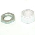
HMN132 |
Spacer
HMW129 |
Cone
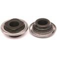
HSA101 |
The parts shown above are common to most models that do not incorporate a brake.
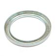
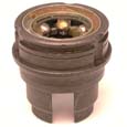
2. Unscrew the right-hand ball ring and internal assembly
Next, use a hammer and punch to unscrew the right-hand ball ring.
Be careful not to snag a spoke with the punch, or you may damage it, or the hub shell.
As you withdraw the internal assembly, try to avoid touching the low-gear pawls while the unit is held sprocket-side up, because there is a risk of the pawl pins' falling out if you relieve the spring tension that holds them in place.
The right-hand ball ring has a two-start thread and must be replaced in its original position, that position must be marked. String or adhesive tape may be attached to the spoke nearest to the letters ' SA' which are stamped in one of the notches on the ring. The whole internal can now be withdrawn from the hub shell. (Installing the ball ring the other way may affect wheel true, but this is rarely a problem in practice.)
This is a standard right-hand thread, turn it counterclockwise to remove it.
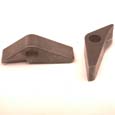
3. Remove the low gear pawls, pins and springs.
The low-gear pawls are the ones farthest from the sprocket. The pawl pins are easily pushed out of the planet cage to release the pawls and springs. Watch out that the springs don't fly across the room and under the bed.
Low Gear Pawls

HSA111 |
Pawl Springs
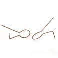
HSA120 |
Pawl Pin
HSA112 |
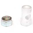
4. Place the left-hand end of the axle in a vise
Then remove everything that is screwed onto the axle: the right hand locknut, spacer washers if any,
cone lock washer and
cone, making a note of their arrangement so that they can be replaced in their original positions.
Right Axle Nut
HMN129 |
Axle Washer
HMW155 or HMW494 |
Locknut
HMN132 |
Spacer
HMW129 |
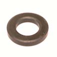
Cone Lockwasher
HMW147 |
Cone
HSA101 |
5. Lift off in the following order:
The clutch spring and cap (cap not shown), the driver, the right-hand ball ring and the gear ring. There is no need to remove the sprocket from the driver unless you are going to replace it. Removing the sprocket is easier in any case when the hub is built into a wheel.
Clutch Spring
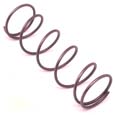
HSA128 |
Driver
HSA123 |
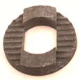
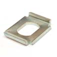
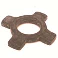
6. Remove the gear ring pawls, pins and springs.
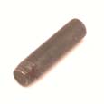
7. Remove the thrust ring, and unscrew the indicator rod.
Thrust Ring

HSA283 |
Indicator Spindle

HSA125 |
Very old hubs had a two-part thrust ring. The old style thrust ring had the same inside diameter all the way through, with a separate thrust ring washer at the end where the clutch spring pressed on it (instead of the section of the part shown with the smaller inside diameter)..
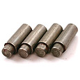
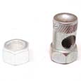
8. Push out the axle key and remove the sliding clutch and sleeve.
Axle Key
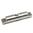
HSA124 |
Clutch
HSA117 |
9. Lift off the planet cage complete.
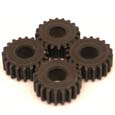
10. Take out the pinion pins and remove the pinions from the planet cage.

Reassembly
1. Left-hand Ball Cup
If the left-hand ball cup has been removed from the hub shell, replace it by screwing anti-clockwise (it has a left-hand thread).
A newer splined left-hand ball cup may be pressed in with an inertial impact alignment instrument (hammer) using care to keep it straight, not crooked. It is a good idea to use a wooden block to spread the force.
2. Prepare the following preliminary sub-assemblies:
- If rebuilding a hub with a drum brake, please read this so you put the brake back together correctly.
- Fit the ball cage into the left-hand ball cup, with the ring of the ball retainer facing outwards and the recess in the dust cap also facing outwards. If a new ball retainer is being fitted, the dust cap also should be new.
- Fit the ball cage into the driver, with the ring of the ball retainer facing outwards and the recess in the dust cap also facing outwards. If a new ball retainer is being fitted, the dust cap also should be new. If the sprocket has been removed, see no. 21 below
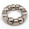
- Fit the balls (only 24, 3/16" diameter) and the inner dust cap to the right-hand ball ring, making sure that the balls can revolve freely with the dust cap in place.
- Fit the pawls, pins, and springs into the gear ring as described in the general instructions to 'The Re-assembling of Sturmey Archer hubs. (The planet-cage pawls, pins and springs are not fitted at this stage.)
- Smear grease in the channels of the dust caps of the left-hand ball cup and the driver and in the recess of the right-hand ball ring. Do not use grease anywhere else. Water-resistant boat-trailer grease is best: see additional information.
- Hold the left-hand end of the axle in a vise, so that the slot for the axle key is above the sun pinion, and fit the planet cage.
- Add the planet pinions and pins. (The small ends of the pins protrude.)
- Fit the sleeve (flange first), the sliding clutch with recess on the flange of the sleeve, and the axle key (with the flat of the key facing upwards), and screw in the indicator rod to hold them in that position.
- Fit the thrust ring and washer, making sure that the flatted ends of the key engage properly in the slots of the thrust ring.
- Fit the previously prepared gear-ring sub-assembly.
- Fit the previously prepared right-hand ball-ring sub-assembly.
- Fit the previously prepared driver sub-assembly.
- Drop the clutch spring over the axle
- Fit the cap (optional -- not really needed) and screw up the right-hand cone finger tight. Then loosen it back half a turn and lock it in that position with the special washer and locknut. On no account must the cone be unscrewed more than half a turn, as that would throw the gear mechanism out of adjustment.
- Invert the assembly in the vise and fit the planet-cage pawls as described in the general instructions to "The Re-assembling of Sturmey-Archer Hubs".
- Remove the assembled mechanism from the vise and, while holding it with the planet cage uppermost, pour about two teaspoonfuls of a good quality thin oil into the cage.
- Hold the cycle wheel in the left hand, with the open (right-hand) end of the hub shell facing downwards, and insert the assembled mechanism from below, screwing-up the right-hand ball ring finger tight only.
- Make sure that the position marks made on the ball ring and the hub flange before dismantling will register properly, and then screw up tightly.
- Fit the left-hand cone, washers (if any), and locknut in the arrangement noted when dismantling, and adjust the hub bearings as described in "The Installation and Adjustment of Sturmey-Archer Hubs."
- If the sprocket has been removed from the driver, fit the outer dust cap over the driver before replacing the sprocket, and see that the dust cap is properly centered on the flange of the driver. Replace the sprocket and spacing washers in the arrangement noted when dismantling, and add the circlip.
- Replace the wheel in the cycle frame and adjust the gear as described in 'The Installation and Adjustment of Sturmey-Archer Hubs.'
Reports of the demise of this Web site are greatly exaggerated! We at sheldonbrown.com thank Harris Cyclery for its support over the years. Harris Cyclery has closed, but we keep going. Keep visiting the site for new and updated articles, and news about possible new affilations.
Thanks to Jane Thomas, who originated these pages,
later revised© 2007 by Sheldon Brown
and 2013 by John Allen
If you would like to make a link or bookmark to this page, the URL is:
https://www.sheldonbrown.com/sturmey-archer/aw.html
Last Updated: by John Allen