
|
|
Tweet |

 [Sheldon used to joke about the "department of redundancy department," yet this section appeared in two different articles. I revised the other version to cover newer hubs before I found this one. I am going to leave this one unchanged. Literary scholars may now compare versions and pass judgment on whether I have enhanced or corrupted the work of the master :-) John Allen.]
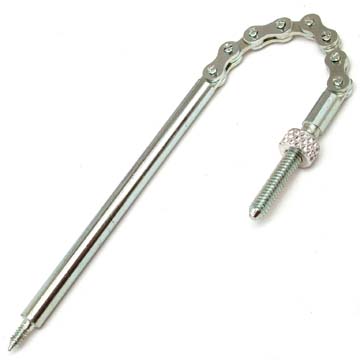
 here is a little chain coming out of the right end of the rear axle, to which the end of the control cable attaches. This chain (called an "indicator spindle " by cognoscenti) screws into an internal part of the hub by rather delicate threads. When you install an indicator spindle, screw it in finger tight, then back it off 1/2 turn. It should not be bottomed out on its internal threads, so that it can swing freely to face the cable. This adjustment must be checked every time the cable is re-attached.
The fine adjustment of the cable tension is accomplished by how far the end fitting of the cable screws onto the end of the indicator spindle chain. The official manuals tell you to adjust it by visual examination of the end of the indicator spindle shaft, but this doesn't always work, especially if the indicator spindle is not original equipment. For best results, adjust the cable by tension. 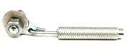 When the trigger is in high gear position, the cable should be totally slack. Shift down to middle gear, while watching the indicator chain-it should clearly move as you make the shift. Then shift to low gear; again, you should see more chain coming out of the end of the axle. Sometimes the internal parts line up in such a way as to prevent downshifting. If you have trouble getting the hub to downshift, turn the pedals slightly forwards. Once you are sure you are in low gear, take hold of the indicator spindle chain and try to pull more of it out of the axle. If the adjustment is correct, you should be able to get just a tiny bit more movement from the chain. If it is completely taut, the cable is too tight. Make sure to tighten the knurled locknut on the indicator spindle so that the adjustment will stay as you have set it.
Double-check the adjustment in all gears. In low gear, you should be able to see that the sprocket moves faster than the wheel, and the hub should not make a ticking sound while being pedaled forward. In middle gear, the sprocket should move at the same speed as the wheel, and you may hear a slow ticking as you pedal. In high gear, the wheel should turn faster than the sprocket. The same slow ticking may be audible in high gear.
If you hold the trigger halfway between middle and high gear, the hub should disengage so that you can spin the pedals forward without going anywhere. If it freewheels forward in high gear, the cable is to tight or has too much friction to release properly. If it freewheels forward in middle gear, the cable is too loose.
--Sheldon Brown
![]()
![]()
I do not recommend this approach, because it presupposes a perfect match between indicator spindle length and axle length. In practice this match is frequently no so exact. If you use the procedure explained above, that doesn't matter.
--Sheldon Brown
The indicator rod of three-speed hubs should be adjusted when the control lever is in the normal gear position, i.e., No. 2. The small locknut above the chain is first Loosened off and then the knurled wire connection is rotated so as to bring the rod into the required position.
With SW, SB, SG, AM, ASC and AC hubs the required position has been obtained when the end of the indicator rod is level with the end of the axle on the left-hand side of the hub.
With AW, AB, AG and TCW hubs it is brought into position by bringing the outer shoulder of the indicator rod level with the end of the axle on the right-hand (sprocket) side. (See B in illustrations.)
![]()
[Several hubs use a special two-piece indicator spindle. The adjustment can be made by Sheldon's method in the lowest gear -- that is, the #1 position -- or as described below. Then check as to whether the hub shifts into all the gears. There is more information about adjusting four-speed and five-speed cables here.
--John Allen]
For four-speed hubs, FW, FM, FC and FG, adjustment is made when the control lever is in the low gear, i.e., No. 2 position (the one next to the bottom gear position). The locknut is loosened off and the knurled wire connection is revolved to bring the end of the indicator rod level with the end of the axle on the left-hand side. (See B in illustration.)
In all cases the locknut must be tightened again after adjustment. If the knurled wire connection cannot be turned enough to give the required adjustment of the indicator rod, the position of the fulcrum (in the case of trigger controls), or the quadrant (in the case of top tube controls) should be moved along the top tube in the required direction, so that the final adjustment may be made on the wire connection as described. At the first sign of the gear slipping in any position, the indicator adjustment must be checked.
![]()
![]()
[Bearing adjustment for internal-gear hubs is also covered in another article -- John Allen]
The hub bearings are adjusted by means of the cone on the left-hand side (opposite side to the sprocket) which automatically adjusts all the hub bearings. It should be adjusted so that there is a barely perceptible sideways movement of the wheel rim.
With brake hubs the left-hand cone projects through the brake plate and is fitted with a slotted adjustment washer. With a rear Dynohub the left-hand cone projects through the armature and is fitted with a slotted adjustment washer. Turning the washer adjusts the cone, which must be locked again with the locknut after adjustment.
When a dynamo is incorporated in the hub the pull of the magnet disguises the adjustment and if this point is not kept in mind the wheel may be over-tightened and the ball races damaged. The position of the armature terminals should be carefully located before the cone locknut is finally tightened.
For all hubs fitted to roadster cycles, the terminals should be parallel to one of the flats on the end of the axle but with forward drop-out lugs they should be turned clockwise through 30° away from a position parallel with the flats.
GH6 lighting sets [front dynohub's] should have the terminals parallel with the axle flats. The notched washer has not been fitted to GH6 hubs since 1954 when the adjusting cone was transferred to the side away from the Dynohub.
Before spinning a wheel to test the output of the Dynohub, ensure that the axle nuts are tight, otherwise the terminals may foul the front fork and be damaged if the axle revolves.
[The following information applies to internal-gear hubs. Old Raleigh front hubs required the right cone to be tightened down -- John Allen].
The right-hand cone (on the sprocket side) is fixed in position when the hub is assembled and must not be disturbed for wheel adjustment in the normal way. When re-assembling the hub after dismantling for inspection or repair, the right-hand cone should be screwed home until it is finger-tight, then unscrewed half a turn and finally locked with the special lock washer and locknut. On no account should it be unscrewed more than half a turn as this will upset the setting of the gears. Wheel adjustment is then made in the normal way with the left-hand cone. If the right-hand cone races are being inspected without removing the internals from the hub shell, the left-hand cone must first be screwed well back so that it does not interfere with the re-setting of the right-handcone.
 When brakes are new they may have to be adjusted frequently (until the shoes have become properly bedded in).
With cable-operated brakes the small locknut (A in the diagram) is first Loosened off and then the knurled adjuster (B in diagram) is tightened until the brake shoes are felt to be rubbing on the inner surface of the hub shell. The adjuster is then Loosened just enough to allow the wheel to revolve without friction, and the locknut is tightened up again.
With rod-operated brakes the adjuster (C in the diagram) is turned until the brake shoes rub on the inside of the drum, and then Loosened off just enough to allow the wheel to revolve without friction. The adjuster is self-locking This is the only point at which the brake should be adjusted. The handlebar brake tubes are only provided to allow up-and-down adjustment of the handlebars.
![]()
![]()
Last Updated: by Harriet Fell