Cyclometer Errors Caused by Magnet Orientation

|
This article describes a subtle speed and distance error encountered with the operation of a Shimano Flight-Deck ® cycling computer on a bicycle with bladed spokes. At low speeds (e.g., less than six mph), the speed and distance readings were too high by a factor of two; at higher speeds, the cyclometer appeared to work correctly. The cause was found to be the orientation of the wheel magnet to accommodate mounting on a bladed spoke such as those used on Rolf Vector ® wheels. The problem was easily fixed by reorienting the magnet. This magnet orientation issue may apply to any cyclometer using a magnet that can be mounted with varying orientation.
The problem was first noticed at low speeds (less than about 6 MPH) and consisted of a speed readout varying erratically between 7 and 12 MPH. Walking the bike resulted in readings anywhere from 5 to 10 MPH, clearly much faster than a walking pace.
In an attempt to track down the source of the error, the number of wheel revolutions for each 0.01 mile on the odometer readout was checked. "Doing the math" shows that each 0.01 mile should be slightly less than seven and a half wheel revolutions. Therefore the odometer should register an additional 0.01 mile every seven or eight revolutions. However, when slowly spinning the front wheel by hand, the odometer registered a 0.01 mile increment every three or four wheel revolutions: it was off by a factor of about two. Yet at more normal riding speeds (10-20 MPH) the speed and odometer readings seemed about right, certainly not a factor of two high.
This behavior could be a bug in the cyclometer firmware or inadequate filtering (de-bouncing) of the magnetic-switch contact signal, but these causes were considered unlikely. Further thought suggested another possible cause: perhaps the errors were related to the orientation of the magnet mounted on the wheel spoke.
![]()
![]()
The wheel magnet assembly for the Flight-Deck™ computer system (and for many others) consists of a circular magnetic disc about 3/8 of an inch in diameter and about 1/8 inch thick. The magnet is mounted in a slotted carrier assembly that is installed on a spoke with a retaining screw. According to the Shimano instructions, the flat surface of the disc magnet should face the sensor switch mounted on the fork. However, to fit the bladed spokes of the Rolf Vector ™ wheels, the installing technician mounted the magnet with the plane of the disc at right angles to the plane of the wheel, so that the round edge of the disc was facing the sensor switch. In other words, the magnet was turned 90 degrees around the axis of the spoke from the intended orientation.
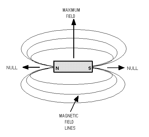
At first glance, this mounting scheme seems acceptable. As long as the magnet passes close enough to the sensor to actuate the switch, the orientation of the magnet should not matter. However, the field around a magnet follows what is known as a dipole pattern. That is, the field intensity is roughly a figure-eight pattern with nulls (minima) in the direction of a line connecting the north and south poles of the magnet, and the maximum fields in the direction of a line (actually a plane) at right angles to a line connecting the north and south poles. (see Figure 1).
![]()
![]()
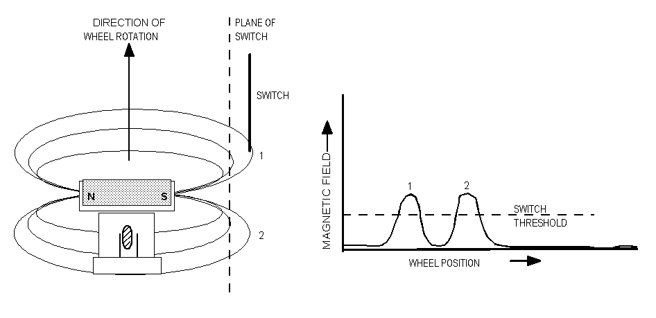
If the magnet is mounted to the spoke with one of the poles facing the sensor, it is possible that the switch will "see" two peaks in the magnetic field each time the magnet passes the switch. This is because of the null in the field along the north-south axis (See figure 2). At slow speeds, when the speed of the magnet passing the switch is relatively low, the switch and the computer circuits actually sense two contact closures. This accounts for the distance and speed being approximately two times fast. As bicycle speed (and hence the magnet speed) increases, the switch and/or computer circuits can no longer react fast enough to sense two distinct closures. Consequently each pass of the magnet registers as one closure, and the readouts become correct.
![]()
![]()
The total error introduced by this "double closure" problem will depend on the ride profile. A ride with a lot of slow sections or stopping and starting will register a higher mileage than a ride with steady, relatively high speeds over the same distance. In addition, the threshold speed below which incorrect operation occurs will depend on how close to the hub the magnet and sensor are mounted, and on the magnet/sensor gap.
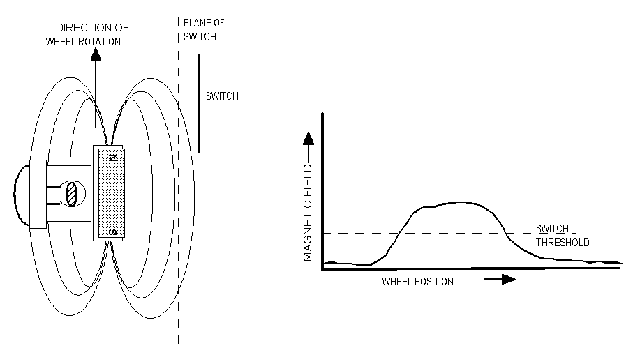
Well, proof of the pudding, etc. A small rat-tail file was used to modify the magnet carrier by enlarging the width of the mounting slot in the area of the spoke. This allowed mounting the magnet on the bladed spoke with the recommended orientation, 90 degrees to the previous installation. Following this change, the cyclometer reliably required 7 or 8 revolutions of the wheel to register 0.01 mile, as it should. Furthermore the speed readout became stable and accurate at low speeds. Clearly the dipolar magnetic field pattern was in fact causing double actuation of the switch. The correct orientation is shown in Figure 3.
P.S. After writing this article, the author got the feeling he probably needs to get out more...
![]()
![]()
HTML conversion by Sheldon Brown
Comment by Sheldon: Charlie Learoyd was a childhood friend of mine, and was instrumental in getting me into "serious" bicycles. My first "sporty" bike, an Elswick Tour Anglais, belonged to him before it became mine. If you care, you can read about it on this site.
Comment by John Allen: The cyclecomputer on my trusty, rusty Raleigh Twenty was showing twice the correct speed at all speeds last Wednesday. I thought that was because I had the sensor magnet installed wrong, as Charlie Learoyd explains. But no. I'd installed a front wheel someone had given me. It already had a magnet and I had installed a second one!
![]()
![]()
Last Updated: by John Allen