Reports of the demise of this Web site are greatly exaggerated! We at sheldonbrown.com thank Harris Cyclery for its support over the years. Harris Cyclery has closed, but we keep going. Keep visiting the site for new and updated articles, and news about possible new affilations.
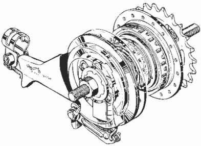
Rebuilding the Shimano Nexus 4-speed Freewheel/Rollerbrake Hub
This article is a translation of the overhaul manual for the Shimano SG-4R31 INTER-4 4-speed freewheeling/Rollerbrake hub gear from German -- the only language in which we could find it on the Internet.
Shimano produced a later model, the SG-4R35. Its parts list shows a few differences. Those we can identify are described in the instructions below.
I thank Patricia Morris for for preparing a draft translation and adding comments. I've reviewed and edited her translation.
The numbers of the steps below match those of the German version, which includes images illustrating the steps. A page with three steps is missing from the German version, but we have included the same steps from the German coaster brake version. Added editorial comments for clarity are in red. Have both German versions and this translation on hand when working on the hub.
Disassembly
of the INTER-4 freewheeling/Rollerbrake hub
Notes:
The individual assemblies of the gear unit should never be disassembled, as this may lead to malfunction.
When parts must be replaced, always replace either the complete gear unit or an assembly.
For disassembly and reassembly of the hub, use 13mm and 14mm cone wrenches (such as Shimano TL-HS10). Shimano recommends grease Y-041 2030, but we prefer more robust lubrication as recommended by Aaron Goss.
Disassembly steps
Clamp the hub axle with the flat sides (drive side) in a vise.
Note: The threads of the hub axle must not be damaged.
Remove the locknut and adjusting nut from the hub axle.
Note: During disassembly, ensure areas A (corners) of the locknut are not damaged.
Remove the bearing retainer A from the hub axle.
Remove the (large black plastic) dustcap (on the drive side) using a flat-blade screwdriver, then pull the hub housing upwards and off.
The complete gear unit can now be replaced (if desired).
Use a screwdriver to remove the 9.6 mm ID circlip (Be careful not to lose it as it flies off. Note that the coaster-brake version of the hub also uses a slightly smaller 9.0 mm circlip. Do not confuse one with the other.)
Slide the return spring unit along the groove in the hub axle upward and remove.
Note: Do not dismantle spring unit. This can make it malfunction.
Turn the (gear changer) sleeve clockwise until it stops and pull upward from the axle. If it does not remove easily, turn the ring gear clockwise.
Turn the planet carrier and ring gear clockwise and remove them.
Using a (small) screwdriver, remove the (large, wavy) ring-gear circlip.
Remove the ring gear. (Note – the SG-4R31 freewheel version uses a ring-gear washer, though the SG-4R35 and the SG-4C35 coaster brake version use none.)
Using a screwdriver, remove circlip C (retaining the 3 sun gears).
Lift out sun gear 3 and sun gear 2. (If you also remove sun gear 1 for overhaul, the timing of the compound planet gears will be lost. See note on our main Nexus 4-speed page for simple retiming. The compound planets can be easily removed at this stage for overhaul by removing the circlip on the bottom - sprocket side -and tapping the assembly sharply to drop out the 3 planet pinions. Remove sprocket first.)
Remove ball retainer 1 from the hub axle. (SG-4R31 only. The retainer is secured to the axle of the SG-4R35 and the coaster-brake SG-4C35) by a clip which is not designed to be removed.)
The dismantling of the INTER-4 hub is now complete.
Assembly of the INTER-4 freewheel-Rollerbrake hub
Clamp the hub axle with the flat sides on the drive side in a vise.
Note: Don’t damage the axle threads.
Install bearing retainer I on the axle flat side down. (SG-4R31 only. The retainer is secured to the axle of the SG-4R35 and the coaster-brake SG-4C35) by a clip which is not designed to be removed.)
Note: The bearing retainer must be lubricated with plenty of hub grease(whether or not it is removable).
Install sun gear 2, gently aligning the teeth with the planet gears. (If sun gear 1 has been removed, retime the compound planet gears on installing - divot on tooth base of each planet gear must face radially outwards from the axle as described on the main Nexus 4-speed hub page.)
Note: The teeth of the planet gears and sun gear 2 must be lubricated with plenty of hub grease.
Install sun gear 3, gently aligning the teeth with those of the planet gears.
Note: The teeth of the planet gears and sun gear 3 must be lubricated with plenty of hub grease.
Insert the (sun gear retaining) circlip in the groove in the planetcage using a screwdriver.
Insert the ring gear and washer in the planet cage assembly. (The internal teeth of the ring gear must face downward. If the compound planet gears have not been timed in step 3, it is almost impossible to mesh the gear ring smoothly with the 3rd gear planets. The SG-4R31 freewheel version uses a ring-gear washer, though the SG-4R35 and the SG-4C35 coaster brake version use none.)
Note: The internal teeth of the ring gear must face downward and must be lubricated with plenty of hub grease.
Steps 7 through 9 are missing from the online instructions, because one page was omitted from the PDF document. Steps 10 through 12 from the instructions for the coaster brake version of the hub are the same, and so we use them here as steps 7 through 9. You may refer to the coaster-brake version of the instructions, in German, for illustrations.
With a screwdriver, install the (large, wavy) ring-gear circlip in the groove in the planet cage.
Install the planet cage assembly on the axle, sprocket side down, while turning it clockwise.
Note: install with light force to avoid damaging the pawls, which would cause malfunctioning.
Install the gear shifter sleeve on the axle, long-blades end down, while turning the ring gear clockwise.
Test: After installing the sleeve, turn it lightly and observe that the shifter ring (outside the sprocket) turns along with it.
Turn the gear shifter sleeve counterclockwise on the axle until it stops. With the tabbed face of the return spring assembly upward (tabs at the sides face downward), align the two lugs on the inside of the return spring unit and the two grooves in the axle with each other, and then side the return spring assembly onto the axle. If installation is difficult, turn the tabbed sprung washer (top) of the return spring assembly counterclockwise while pressing the assembly down onto the shifter sleeve.
Note: Lubricate the spring unit with plenty of hub grease.
Check: When the spring assembly is installed, the axle groove for the retaining circlip must be visible.
Reader Elmer, from the Netherlands, adds the following comments:
During assembly I experienced 1 problem with step 10 and wanted to let you know how I solved it.
I couldn't get the return spring unit into place, so I followed the instruction above (turn the top washer counterclockwise). Unfortunately this caused disassembly of the unit itself. So you have to be very careful. I have managed to assemble the spring unit back together. First assemble it without any tension on the spring (there is only 1 way to connect the 2 washers with the spring in between). This way you know how the 2 washers connect. Then I used 2 pliers: 1 to hold 1 washer and the other to turn the other washer counterclockwise (in total 360 degrees). Actually you have to turn a little bit further, press the washers towards each other and then release it. If you do this right, the 2 washers will be connected again. This is somewhat delicate as to much movement will free the spring.
To get the spring unit in place, I kind of wiggled it into position instead of really turning it counterclockwise. And yes, it works again.
Install the 9.6 mm circlip in its groove in the axle. Using the mouth of a 19mm open-ended wrench is a good way to push the circlip into its groove without distorting or losing it. The coaster brake version also has a slightly smaller, 9.0mm circlip. Do not confuse the two.
Lower the hub shell over the gear assembly, turning it gently counterclockwise to seat it.
Reinstall the (large black plastic) dust cover A on (the drive side of) the hub housing.
The inside of the dust cover A must be lightly lubricated with hub grease in order to prevent the intrusion of water.
Press the dust cover A firmly onto the hub housing until it locks audibly into place.
Check: After installing the dust cover on the hub shell, test whether the shell can easily rotate counterclockwise.
Install bearing retainer B in the hub shell.
Note: The bearing retainer must be installed with the ball side down, flat side up. Use plenty of grease.
Adjust the axle nut for easy rotation with minimal play and secure it with the left cone locknut.
Reports of the demise of this Web site are greatly exaggerated! We at sheldonbrown.com thank Harris Cyclery for its support over the years. Harris Cyclery has closed, but we keep going. Keep visiting the site for new and updated articles, and news about possible new affilations.