published in Radfahren 2/1990, pp. 44 - 46
Translated by Damon Rinard and John Allen from the original German at:
https://klara-agil.de/die-fahrwiderstaende-in-formeln.html.
![]()
(Numbers in parentheses refer to the associated bibliography)
Other articles by Rainer Pivit published in "Radfahren" magazine:
![]()
In science and technology it is usual to "illustrate" nature and technology using mathematical constructs. Abstract formulas describe all of the forces which affect the bicycle, those the bicycle rider welcomes - strong tail winds or a downslope - as well as ones that make him groan - for instance ascending for hours with a heavily laden bicycle in sweltering heat.
The force resisting the motion of the bicycle Ftotal consists of the sum of rolling friction Froll, aerodynamic drag Fwind, the force needed to accelerate Faccel, the upward slope resistance Fslope, bearing friction resistance and loss due to the drivetrain efficiency factor η [Greek letter eta]. Unlike the other quantities, acceleration and upward slope resistance can also be negative - usually a positive thing for the cyclist - propelling rather than retarding the bicycle. Naturally, the drive losses apply only if the cyclist is pedaling. Bearing friction, such as friction in the hubs, is usually combined with rolling friction; similarly, the bearing friction forces in the drivetrain, specifically, pedals, bottom bracket, freewheel and partially also the hubs (the additional forces on the hub due to chain tension) are calculated as they affect the drive efficiency η. Thus one arrives at the formula:
| Ftotal = (Froll + Fslope + Faccel + Fwind)/η | |||
| where | η : | drivetrain efficiency, dimensionless. | |
| The individual retarding forces are described as follows: | |||
| Froll = cr m g | where | cr : | coefficient of rolling resistance, dimensionless |
| m : | total mass of the vehicle with driver in kg | ||
| g : | acceleration due to gravity » 9.81 m/s2 | ||
| Values for cr for typical bicycle tires and surfaces range between 0.0015 and 0.015. | |||
| Fslope = s m g | where | s : | upward slope, dimensionless |
| Faccel = a m | where | a : | acceleration in m/s2 |
| Fwind = r cw A vwind2 /2 | where | r : | density of air in kg/m3 |
| cw : | coefficient of wind resistance, dimensionless | ||
| A : | frontal area in m2 | ||
| vwind : | wind velocity in m/s | ||
| The power required to overcome the total drag is: | |||
| P = Ftotal v | where | v : | velocity in m/s |
The formula for air resistance applies strictly only if there is no wind. If there is wind, the vector sum of wind due to motion of the bicycle and true wind is to be taken instead of v; however cw and A are valid only for incident flow normal to the front. A description of air resistance which is a good approximation of reality (and is consistent with the measured drag with wind) is complicated (1, 20).
The bicycle's drivetrain efficiency η amounts to about 96% max. A derailleur gear system reduces the efficiency only slightly by an additional 1 to 2%. Internally-geared hubs have efficiencies between 95% in direct drive and 80% in the worst case. The efficiency of dirty and rusted bicycle chains is not well-known.
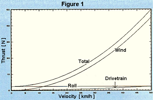
In what follows here, the assumptions are made of no wind, no upward slope and no acceleration. Figure 1 shows the drag as a function of speed for a typical conventional racing bicycle, and the effect of the individual retarding forces. It was calculated using:
η = 0.95; m = 80 kg; cr = 0.003; r = 1.2 kg/m3; cwA = 0.39 m2

At approximately 12 km/h, rolling and air resistance are equal. At higher speeds, air resistance is strongly dominant.

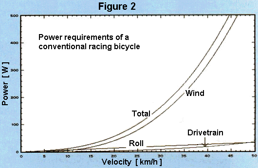
Figure 2 shows the required power output as a function of speed for the same bicycle. A typical rider can maintain 80 W continuously on an ergometer. Observations in traffic however show that riders there often ride in a range up to 200 W. Probably this is attributable to better cooling by the wind, the highly variable application of power in traffic conditions, and stimulation by the surroundings. Top racers can maintain about 500 W for one hour.
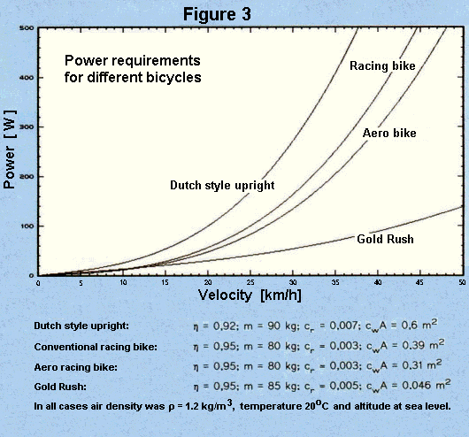
Figure 3 shows the power needed to propel different bicycles with a male rider.

In normal riding, a bicycle cannot proceed at a constant speed. Travel is stopped or slowed over and over due to intersections and various other obstacles and disturbances. To that extent, acceleration work is not to be neglected, at least not in city traffic. Kyle calculated the energy to overcome the individual retarding forces for a trip on a touring bike assuming a constant power input of 187 W - this corresponds to a speed of 32 km/h under ordinary conditions (14). He assumed that there would be a stop every 400 m. Under these conditions 53% of the energy goes into air resistance, 11% into rolling friction and 36% into acceleration work. Thus aerodynamic improvements should not result in any excessive increase in weight.
![]()
![]()
© by Rainer Pivit, 08/98
![]()
Last Updated: by Harriet Fell